Game on!
With some excitable chatter, I enticed Jenny into the shed and stood beaming with glee as she took on a game of Uo Poko ("Puzzle Uo Poko").
I noted that having the windscreen in actually improved the bass sound from the wooffer - maybe it acts as a sound surface or something, but you know what, it was great.
I went on playing into the night and, amongst other things, totally trounced my Galaga high score. That game rocks.
Jenny finally ejected me verbally at 10:30 as I needed to be up at 6:15 for a trip to Cambridge the next day.
So, if I can sort out that bezel, add a few touches of black masking tape, improve the back door hinges, create a holster for the light gun, clamp the coin-encoder wires down, hook the wire up to the door, connect the 12v molex to the coin slot light, airbrush some side art and black out/cover the edges of the monitor and its power LED..
It plays and it plays well. From here on in pretty much everything is a bonus. I think can safely say it's fit for purpose and move on to the final details.
Wednesday, May 30, 2007
Windscreen
Having cable-clipped the wireless receivers and USB hub to the inside shelf under the coin door to stop them falling into the bottom of the cabinet, and fiddled about trying to screw the keyboard encoder in (turns out partially knocking in a nail and removing it is a good way to create enough of a pilot hole to get a self-tapping screw in) it was time to go for gold - the last remaining major component - the windscreen.
I measured up my A3 piece of blach card and found that it was an inch wanting on all sides. Ho hum. At least it was only 75p. I decded to do a practice run with it anyway and used 2 by 4 and a glass pot from a Gu pud to get the straight edges and rounded corners respectively. I then used my new stanley knife to cut out the centre and voila, one bezel.
Back to the shed and I don't know how I mis-measured it but it was a dead loss! Never mind. I ditched it and decided to put the glass on, at least temporarily. Havind impatiently already fitted the mirror, and with the machine running, I did my best to trap sawdust as I piloted the screw holes.
I almost suceeded and blew the rest away with a few huffs and puffs. After another glass-cleaning session, I had to flip the windscreen round to every possible orientation in order to find the one that matched the drill holes.
Finally, in with the screws. One was scraping against the glass so I filed the hole sideways with the drill and got the screw into a decent positon. Job done.
I now had, but for a bezel and a few items on the snagging list, the arcade machine I have been working to build for 18 months. Whew.
Coin door elctronics
The coin door has a real mech behind it and correctly validates 10p coins. When the correct coin goes through, it triggers a microswitch. Nice. However, that click ultimately has to press a key on the keyboard to notify that a coin has been inserted. I use the term electronics looseley, as I didn't do any actual electronics myself, but it took some doing to create an intermediary that would be abte to communicate between the door and the PC.
First things first, the X-Arcade owns the PS2 port. No point trying to change that. It has a PS2 pass-through (also used for programming the buttons) and I had an old PS/2 keyboard I could hack. However, pull out the joystick to fit the wheel and you either lose the coin door or have to do some rewiring. Ugh.
Add to this the wireless keyboard and mouse combo needed both USB and PS2 to function and it was clearly time for a visit to PC World.
I'm not a fan of the place, I think it's overpriced and stuffed with unemployable teemagers who can't spell "PCs" and, despite the marketing, really isn't that helpful for non-computer literates, taking advantage of them in that standard ugly "good business" consumer way.
However, I wanted some gear and I was prepared to pay a little extra not to have to wait a week before being able to move ahead. In fact, I don't have any clear weekends left before the party, so this is pretty much it.
I laid my hands on the cheapest USB keyboard I could find. At £6-something it was going to be rough, but I just wanted that USB interface and keyboard encoder. RSI, comfort and style were not considerations today.
As it happened, I also found rather good looking wireless keyboard and mouse in aluminium with a single USB dongle for about £30. I barely hesitated. With Logitechs going up to £150, this seemed a bargain for something that a) wouldn't be seen much and b) looked allright even if it was. I just hoped it wasn't rubbish. I grabbed a USB hub whilst I was at it and headed home to do some wrecking.
I was surprised at how many screws there were in the bottom of the cheap keyboard (surely that drives up the price?) but I soon had it in pieces. Now I discovered how they make 'em so cheap - there are no switches. Nothing to hook the coin door up to. Rats.
The internals of the keyboard consisted of one tiny PCB and three sheets of plastic. It is a fiendishly good design. 3 independent layers of plastic. Top and bottom layer have PCB-style conducting tracks painted on them and the middle layer has holes in it at opportune points. The middle layer acts as an insulator and spacer. When you press down on a key, it pushes the top and bottom contacts together through the spacer hole.
Ingenious, but how was this goung to work for me. Short of sellotaping wires between the sheets, it was looking a bit grim. So much for cheap keyboards.
I puzzled over it a while and then realised that all the tracks led back to a couple of dozen contacts on that tiny PCB. It seemed that connecting the right pair combination of contacs would give you the keystroke you want.
So I spent half an hour tracing the tracks. It was tough going. i decided to use dabs of permanent marker to stop me squinting and losing track (bu-bum) of where I was.
Finally, I had identified the pins - 3 from the left and far-right. I popped the board out and stripped down an old CD audio-to-motherboard cable to make the connections.
Before setting to work on the precise pins, I gave it a go on the machine. PCB in one hand, I plugged the lead into the PC and up popped the little installation baloons. Once completed, I opened Notepad and used the two ends of the wire to scrape across the pins.
Supe enough, I got some characters output on the screen. Hurrah. I must have done something unusual to it because the next thing I knew, the machine had shut down. Hmm. Not sure what I touched there, but the principle was sound.
I set to with masking tape and scisors and soom had the wires all bandaged into place. I plugged it back in to the machine and touched the exposed tips together as if connected by the microswitch and.. nothing. Seems the sellotape was a bit loose.
A few adjustments later I had better luck. When I later mounted it into the cabinet, I had the same problem again. I think I need some mini clips over the masking tape to clamp the wires to the pins.
Top tip of the encoder was this, though: before sellotaping the wire to the pins, cut some small pieces of tape and cover up all the other pins so you can be in no danger of contact. Had I not done this, it would have been infuriatingly fiddly to tape the wire to one and only one pin. As it was, I coul splash the wire sideways across the pin and jam it down. Nice.
Marquee graphics
Having become very excited upon first hanging the graphics over the strip light and then again when I put the marquee between the sheets of glass, it was finally time to mount it.
Starting with the lower retainer, it lined it up, drilled in and screwed it into place. I had worried that the speaker cloth would catch on the drill bit and get dragged and twisted, but it was fine. I just held it firmly and started the drill slowly to make sure.
It was a fiddly business measuring upside down with one hand to find where the screws could reach wood, whilst holding the retainer, marquee and glass in place with the other. Because of the angle of the wood against the glass, I had trimmed the bottom edge to give a better contact, but this moved the usable screw-point back from the edge and, with the with of two sheets of glass and the marquee approaching a centimetre, the screws had to go in 5 mil from the edge of the retainer and only just into the edge of the wood.
Fortunately it's a bit tight on the glass up there so it wasn't bearing much load and held nicely. To help hold the retainer in place while I was fixing the screws, I hammered small nails though a couple of the pilot holes, just enough to hold it. When the first two screws were in, out came the nails so I could do the last two. Once the lower retainer was in place, I spent time cleaning and dusting the glass and then slotted it into place. Oh yes, looking good.
With the aid of a small step-ladder, I climbed up so I could lean over the top to get the upper retainer into place. Aside from one very stubborn screw that wasn't moulded quite right and needed to be discarded, the upper retainer was a breeze. A few pilot holes, four screws and it was done. I used the nail trick again to hold it in place.
Now it seriously looks like an arcade machine, not just a home-made wooden box!
Fitting T-Molding
Ladies and gentlemen of the cabinet-building class of 2007, if I could offer you one tip for yor project, t-molding woud be it. The long term benefit of t-molding has been proved by these pictures, whereas the rest of my advice has no basis more reliable than my own meandering experience. (If you don't get it, shame on you. Search for Baz Luhrman)
Wow. This really did it. I'm not quite sure why, but banging in the t-molding turned the cabinet from a somewhat convincing black box into an actual arcade machine. It may only be a strip of red plastic, but sometimes it's the details that make everything sing.
I once again heartily commend to you the inexpensive CD I got from spystyle on eBay. If he ever stops selling it and is willing, I will happily redistribute it for him! He has some simple and effective advice about clearing out the router slot and cutting the fin on the T-Molding.
I got the first section in with a picture-hook hammer and an offcut of the speaker cloth. It worked, but I could tell it wos damaging the finish slightly. You really do need a soft mallet. Serenipitoustly, B&Q sell a white, non-marking rubber mallet for about £7. Perfect and worth every penny, even if it is used for only an hour or so. No marking, no damage, just a bit of rubbed off rubber that you can wipe down.
I wanted the edging all round the sides as the bottom edges do tend to get scraped, what with the low clearance. How do you get a mallet (and me) underneath a 1" groud clearance to pound in some trim when there is a half-tone monitor loose and trapped in the box?
Well, you can't lay the cabinet down, that's for sure. You can't swing a mouse, never mind a cat in that shed with an arcade machine in there. I resorted to tipping it up against the walls and shuffling the base out until it balanced, then crawling underneath. Dangerous? Why, of course. It would'nt be fun otherwise.
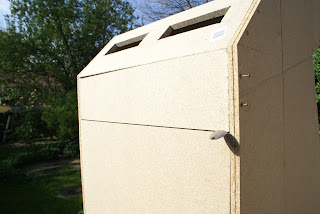
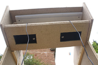
These are a couple of shots to show it off. Note the hole for the mains wire by the air intakes at the base.
Wednesday, May 09, 2007
Paint round 3
Having spent the best part of 2 days of a 3-day bank holiday weekend on the cabinet, it was a bit much to hope for some Monday action, what with a house to run and my wife to hang out with.
However, as luck would have it, Helen and Ben were coming to dinner and Jenny asked them to come early so she could spend an hour measuring and fitting the clothes she is making and altering for Helen.
Ben and I retired to the garden to chew the fat with a pair of half-litre Sam Smith's organic lagers. I got a good hour of mucky brush-work in while Ben stood back to avoid getting paint on his evening shirt.
The aim here was to cover all the corners and tricky bits so that I can then roller the larger surfaces. I managed to get most of the way through it before the ladies rang the dinner bell.
These are the shots I managed to get after another glass or two of wine.
Monday, May 07, 2007
Start painting
Ok, so it's getting dark, I've finished the last bits of building, hoovered out the cabinet again, sanded it down (boring, but it's one of those things you can't go back and do later). The sun has definitely set, but me, I'm impatient. Give me 5 minutes of sunshine and I'll star an hour's job.
So, out with the paint again. By the time I was half way through, I had to bring out a light from indoors to work by.
Here's a shot of the results:
Sunday, May 06, 2007
X-Arcade wedges
The front of the cabinet holds the X-Arcade beautifully, but there are a couple of inches of play. Not good if you are taking on the end of level boss, so time to wedge it in. I decided to go for a couple or blocks of wood, with the edges routed to a curve.
Here's the resulting blocks:
I made the blocks out of the same wood that is used to lash the parts of the side panels together.
It's close, but just a little too wide, so the X-Arcade didn't fit between them (by literally a couple of mil each side).
Result? time to do something very dangerous with the jigsaw to trim these tiny lengths of wood. I'd say "don't try this at home" but, to be honest, I don't believe in health and safety, so if you do have to do something similar, use your noodle to avoid staining the wood. And if you are stupid, well, Dawkins and I do agree on the odd point.
Here's a shot of the fitted wedge. Interesting angle:
Monitor cross-bar
Now here's a thing. After a year or so in the shed, wood warps. No, really, I kid you not. You thought it was machined nice and straight and it would stay that way? not so.
Net result is the cross-bar that holds the monitor in place and prevents it sliding off the angled supports, despite being precisely cut by a delightful if grumpy old giffer at B&Q, looked too short. However, I know I measured the cuts and they were right on.
Taking a good look at the wood, I could see it had bowed out between the hinges of the back door. So the quesion is, go with the bow and leave a bit of naked screw thread hanging in a gap, or take the opportunithy to pull things together and try to reverse the process?
I believe that, a bit like Jenga, it's best to keep things as straight and precise as you can, for as long as you can get away with it. Once things get wonky and you start operating (with some imprecision) relative to a wonky reference, it gets messy in a hurry. So I decided to pull things into shape.
At this point, I had to ask Jenny to lend a hand because, having fitted the back door, I couldn't now reach around it to push in the side of the cabinet whilst holding the cross-bar in position for tacking. I was glad to be able to involve her.
Having tacked both sides, I set about getting the left side screwed in properly, with pilot holes and countersinks. Once this was done, it was time to try for the other side. What I have found with tacking is that it tends to leave a gap because the screw is threadding its way throuih the first piece of wood, but dos not immediately catch onto the adjoining piece so, for a turn or so, it pushes the second piece away, leaving a gap.
This isn't normally a problem as the objective is to hold the other end of the wood in place whilst you are properly and precisely fixing the first screws - it just stops it moving around and getting damaged. The end you are working on can generally be unscrewed and re-tacked, this time without a gap, whilst you seat the first screw.
In this case, the door got in the way again, and Jenny was into her dress-making so I didn't want to disturd her. Given that one side was already screwed in flat, I decided to lie the cabinet on its side and put the monitor on top. Needless to say, the weight of the screen was certainly enough to apply the necessary pressure to finish the job.
Painting!
For me, the big milestone was the paint. You can't paint until you're finished building. Well, not quite. I decided to start by painting the base as that bit is finished and isn't likely to be seen again after PC, glass and mirror are installed. Time to get it done with a one-coat lick of paint bscause I like to know that things behind the scenes are done.
Here are a couple of shots of how it turned out:
Air intakes
Final cut for the main body was the ventilation holes to draw air in at the bottom. Unfortunately, the base and its 2 by 4 reinforcing struts were in the way of the jigsaw blade. I took one look and was very happy that I used screws. Out they came, off came the panel and in no time at all, they were done. The alternative was an hour with a hacksaw blade between my fingers. No way.
It was a simple process of measuring to get the vents located centrally and evenly spaced, drawing round the vents, measuring inwards from the outline to leave enough wood for the screws and just open up the area behind the actual vents, drill the four corners of the marked area to get the jigsaw blade in, cut between the drill holes and sand down the edges. Job done, panet screwed back in and voila.
Hinges
Hinges are tough. No two ways about it. You have to be absolutely spot on and square on, or they just don't work. Having spent a good deal of time lining things up and ensuring that they were right to the half-millimetre, I screwed the first one into the cabinet body.
The second hinge, I discovered that I had piloted too far in. Fortunately, you can move the hinge along about a centimetre and retry. This covers up the missed pilot holes. Cunning. In it went, just right.
Satisfied, I flicked the hinges and realised I had screwed them in upside down. There was no way to attach the door. Rats. Out they came and back in the other way up. Phew.
The hardest part is balancing the door to attach it to the hinges. With the cabinet flat, I balanced and tweaked until I had it. Unfortunatelt, the door was too low on the first try, so out came the screws and, by more luck than judgement I turned the wood over to expose the un-piloted opposite edge and this time everything worked.
The only fly in the ointment came when I stood the cabinet up and realised that B&Q hinges have a few millimetres of play, so the door drags on the bottom edge. Ho hum. Good enough! I did a bit of sanding to ease things but that will just have to be a feature!
Trimming the top of the back door
Checked the back door, too big for the hole. Hmm. Need to lose 4mm off the height. Router seems like a good substitute for a plane, so I set to. Trouble is it's not all that steady and the guide ends up at a different level behind the bit than in front (becuse the bit has cut away some of the wood). Not looking good.
Time to get the jigsaw out again, with the 2-by-4 as a guide. It vibrates and moves around so I have to squat on top of the 2 by 4 to keep it from buzzing out of place. Job done and it looks passable. I think that end will be the bottom of the door.
I line everything up, stick an old teaspoon in the gap to stop it falling down and, wow, a lintel that looks distinctly like it will pass muster. Nice.
Back door lintel
This is a relatively quick one. Routed to one depth rather than two just to fit with the rear ventilation panel which was routed to depth two. Tack it in, pilot holes, countersinks, four screws should do nicely. Just have to make sure it lines up with straight dignity to the back door - I don't want a slanting gap.
After all my dad was a civil engineer with a perfectionist's eye, so it would never do to disrespect the family tradition with a wonky lintel.
Rear ventilation
First step, use the router to get a bit of diagonal on the edge so it will fit with the rear panel above the door. Next, measure up and draw around the vents. I like to draw around the actual object that is going in as it saves measurement errors (it saved me a headache for the speaker panel).
I took the location of the vents from a picture I found on the Web of the back of an actual Defender cabinet. It's great that there's so much information out there about this particular model.
Finally, drill pilot holes for an easy life, fit one of the vents, take a photo and then realise I need to paint it, so take it out again!
Finally, drill the holes in the cabinet walls and, with a bit of balance and skill, tack the panel into position. A few pilot holes and countersinks later, we're all done.
Speaker mounts
The speakers sit quite nicely into the holes in the speaker panel and would not fall out under normal use, however, this is going to be properly used, so they need some support. After all, if one popped out during a particularly energetic bout of X-Men vs. Street Fighter, it could fall and injure the mirror.
Trying to finish your opponent whilst peering down on to an upside-down, back-to-front screen with shards of mirror on it would be pretty tough.
I went for some small corner braces but declined to screw into the speakers themselves as I didn't want to damage or alter the acoustics. These bad boys should hold them in place nicely, but I may add elastic bands or cable-ties just to be sure.
I also bent them inwards ever so slightly (making an obtuse angle as Phil reminded me at the pub the other day) to give a good grip. The corners of the brackets are a bit sharp and scraped the speaker casing, but they aren't going to be seen, so not an issue.
Here's the end result. Eight brackets just waiting to take the speakers. There is a certain frustration in building the box and collecting all the accessories but not being able to put it all together until after the painting is done. Still, it will teach me patience.
Thursday, May 03, 2007
Monitor supports
The monitor is a 21" CRT ton of a thing, so the monitor supports need to be pretty beefy. It is also a bit narrower than the cabinet itself, so needs the supports to reach inwards and hold it up.
The upshot is that a couple of bits of 2 by 4 fixed by their narrow (the 2) edge are about right, but too flimsy to hold the weight. The plan had been to support them from the floor, but with the monitor needing to be at an angle to keep it out of sight of the player, this was looking increasingly complex.
In the end I settled on this design - effectively a pair of small stools screwed to the sides of the cabinet. It's a remarkably sturdy structure and I was able to stand on them and do press-ups off them without them moving.
To get the angle on the monitor, I had put a bucket upside-down inside the cabinet and balanced the monitor on top. Slightly precarious, but by chance it gave a good angle, so I measured it up and set about getting the struts cut. B&Q's cutting service is great - saved me a lot of time.
I routed the inside-top corners of the two supports (you can probably just make it out in this picture) as they were just a few mil too wide to hold the monitor. 20 big screws and countersinks later, it was done.
Tuesday, May 01, 2007
So here we are, the Arcade cabinet is progressing nicely and, barring any unforeseen design hiccups or gross mis-measurement, it should be ready in time for the party. Here are a couple of shots I took that really show off where it is headed.
First up, with the X-Arcade, graphics and coin door (from gremlisolutions.co.uk):
Here with the X-Arcade removed and switched to the steering wheel (many thanks to Chris Winfield!):
And finally, looking really tasty in the dark:
First up, with the X-Arcade, graphics and coin door (from gremlisolutions.co.uk):
Here with the X-Arcade removed and switched to the steering wheel (many thanks to Chris Winfield!):
And finally, looking really tasty in the dark:
Subscribe to:
Posts (Atom)